Leeza SOHO — walking the completed building
Six minutes in the finished tower, and how the coordination model was tested in mock-up, fabrication and construction.
From computation to construction
I worked on Leeza SOHO from the competition in 2013, initially as design lead, through to completion in 2019, becoming project architect as the project developed and relocating to Beijing to carry it through design development, documentation and construction. The project became an unusually direct encounter with the consequences of computational design: the same geometric systems that controlled the digital model eventually had to be translated into façade components, structural assemblies, fabrication processes and construction sequences.
As Project Architect I worked with consultants, the client and contractors through design coordination, façade mock-up reviews, value engineering and site supervision. Those encounters were continuous feedback between the digital development of the building and its physical realisation.
A computational model became the project's coordination instrument.
The project was developed through a large Grasshopper definition linking the primary geometry to a range of downstream systems. The sequence below shows one aspect of this process: the basic geometry is generated and manipulated while the façade system responds to changes in the underlying geometry.
The primary geometry was carried by a small team. I developed the overall design and the Grasshopper system that linked massing, façades and project information, and built the detailed models for façades FS1 and FS2. Kaloyan Erevinov, as the other main geometry lead, modelled FS3 and FS6 in Digital Project, where the atrium–core intersections produced a less regular envelope that resisted the same automation; he also took on parts of the lobby interiors and was central to reviewing façade detail-drawing packages. Pavilion façades, other interior areas and landscape were only partly scripted and mostly modelled by hand. I coordinated those packages and, late in the job, substantially reworked parts of the basement-to-ground lobby interiors as well as the landscape.
The 3D model did not contain the last screw. What it could hold was coordinated geometry and design intent. Façade detail drawings carried the construction truth further, and the façade contractor developed its own Digital Project model from ours. Automation did not eliminate specialist modelling or drawing; it changed how a small team organised them while requirements kept moving. The practical limit was not what could be scripted, but how much complexity could be developed, maintained and verified across model, drawing and site.
From digital model to physical system
The digital surface was not itself a construction method. Each façade system imposed different constraints on panel size, curvature, tolerances, assembly and installation.
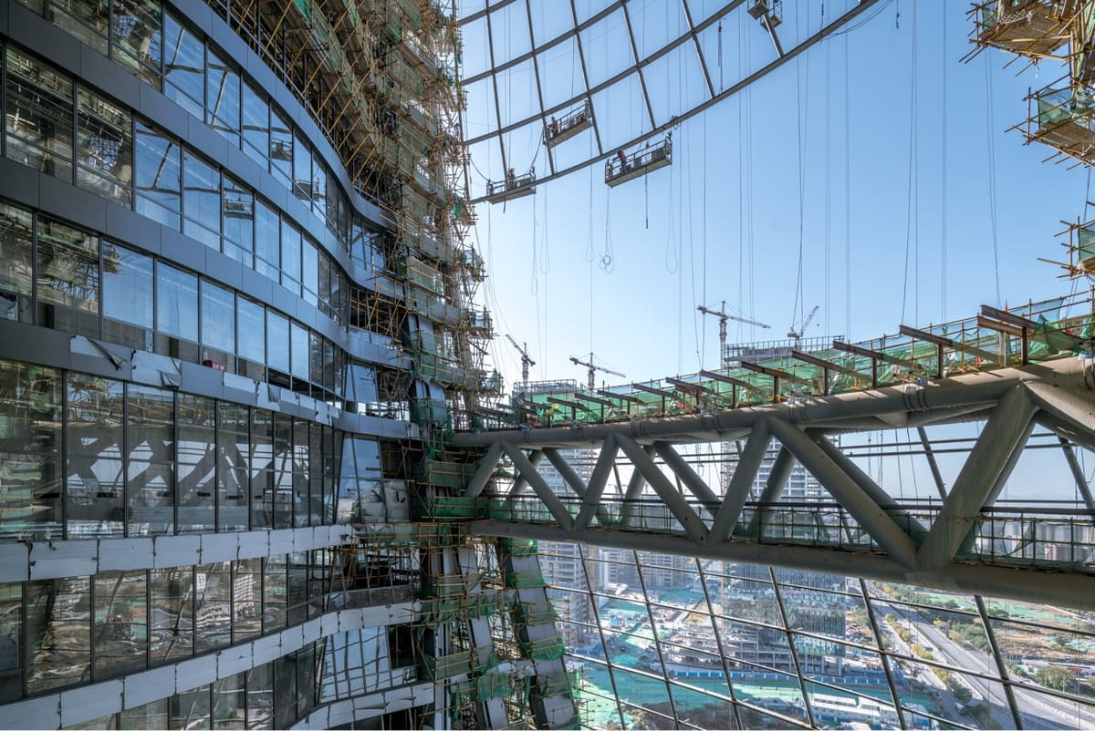
Façade System 2 (FS2), for example, used flat glass panels that were cold-bent on site. The subdivision of the surface therefore became a question of manufacturing and installation rather than purely geometric resolution. At the same time, achieving a lightweight and transparent structure required the façade, its support structure and the installation sequence to be considered together. The resulting system suspended the façade from bridge trusses while transferring lateral loads to the adjacent main columns.
The project also involved physical testing at scales where the digital model ceased to be sufficient on its own. FS1, FS2 and FS3 were tested in large-scale mock-ups before tendering. These tests informed details ranging from the final colour and appearance of the systems to the selection of connection hardware for FS2. They also exposed practical issues in assembly and detailing that were difficult to anticipate from the digital model and drawing details alone.
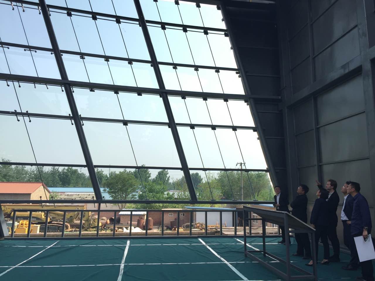
For the structural system, the building was also tested as an 8-metre-tall physical model on a shaking table as part of the structural verification process.
Source: China Academy of Building Research (CABR)
From model to building
The value of the computational model was ultimately tested outside the computer. Construction introduced material behaviour, tolerances, sequencing, labour, cost and regulatory requirements that could not be reduced to geometry alone.
The project taught me that maintaining a relationship between digital modelling, physical verification and construction can be more consequential than increasing the sophistication of any individual model.
The building in 2022
The following footage was recorded in 2022, when I was able to revisit the building after its completion in late 2019.
Construction timelapse, 2017–2019
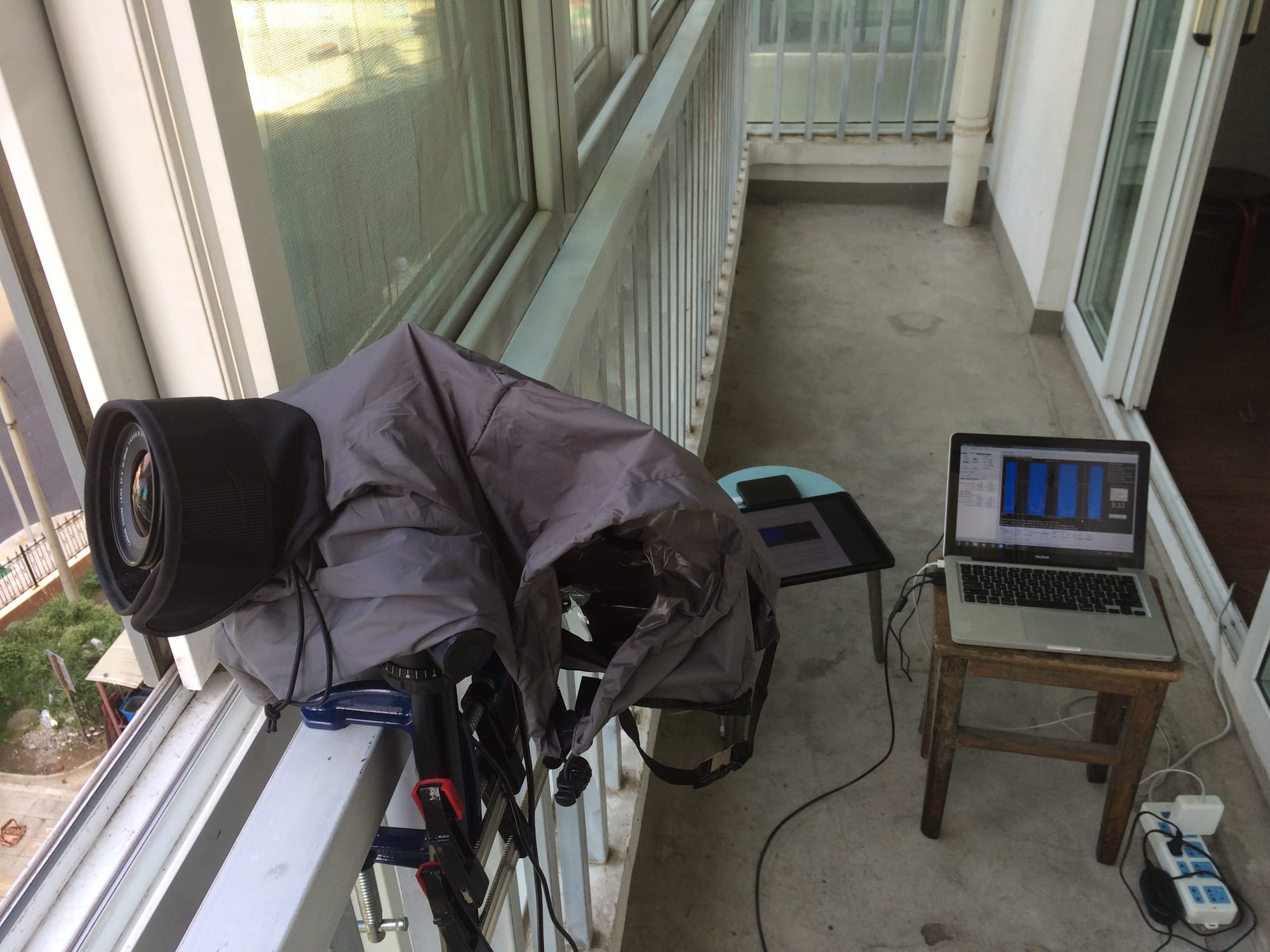
I set up a camera overlooking the construction site from an apartment in the adjacent building and recorded the construction process over 2 years. The footage was subsequently assembled into a timelapse.